Index to this Page
| Overcurrent Protection | AC Wire/Cables | ||
| ELCI: Elect Leak Circuit Interrupt | Isolation | ||
| Distribution Panels | References | ||
Basic Electricity - Page 8 - AC Circuits Continued
Basic electricity for boat builders, boat repairers and owners. What you need to know about the electrical systems on your boat. Overcurrent Protection, Distribution, Wire, Isolation, transformers.
On Board The Boat.
Overcurrent Protection:
Now that you have the power on the boat, where do we go from here?
The first thing that should come after the shore power inlet is the main circuit breaker for all AC power on the boat. This should be a double pole circuit breaker, that is, it breaks the connection in both the black and white, the hot and neutral wires, at the same time. Marine Ignition Protected, Manually Reset trip free circuit breakers are required. Do not use household circuit breakers. See Over Current Protection for a description of a marine ignition protected manually reset trip free circuit breaker.
In DC circuits, single pole breakers are used that only break the positive side of the circuit, but they should not be used in AC circuits. The reason for this is if there is a fault in the circuit and only one wire is broken, you could still have a hot circuit.
The main breaker should be as close to the power inlet as possible. The power inlet is considered the source of power and as we learned in DC circuits the overcurrent protection is required to be within seven inches of the source of power. This protects the wire and prevents fires due to overheating. Remember, these should be marine, ignition protected, trip free circuit breakers..
Sizing The Circuit Breaker: The rating for the circuit breaker in an AC circuit should not be any greater than the maximum current
rating of the conductor. If it's a 20 amp circuit, it should have a 20 amp circuit breaker. A 30 amp circuit should have a 30 amp circuit breaker, and so on.
DO NOT size them to 150% like in DC Circuits.
DO NOT use fuses in AC circuits.
All parts of the electrical systems should be marine rated or UL - Marine Listed. This is for your protection. Household devices are not designed to operate in the damp marine environment, and circuit breakers used in homes are not ignition protected and are not trip-free. Metal parts will quickly corrode. This results in bad, high resistance connections, and heat. Corrosion is a real problem with electrical equipment on boats.
AC circuit connections, plugs and contacts, should be inspected and cleaned on a regular basis. Many boat fires over the winter are caused by the shore power inlet connection on the boat getting too hot due to bad or high resistance connections from corrosion.
ELCI: Electrical Leakage Circuit Interrupter
Combined with the main circuit breaker should be an ELCI (Electrical Leakage Circuit Interrupter). An ELCI detects current leaking into the water. It does this by measuring the current in the black (hot) wire and the return current in the white wire (neutral). If everything is ok the difference between the two should be zero. If there is an imbalance, that is, less coming back than is going, and this imbalance is 30 ma or more for 100 milliseconds then the ELCI trips and shuts off all power. This is to protect people in the water, or touching metal that is in contact with the water. See here for more on ELCIs Sounds like a GFCI? A GFCI only protects the single circuit it is on and does not prevent current leakage into the water. An ELCI protects the whole boat and shuts off all power to the boat.
Distribution Panels:
The wire leaving the main breaker should go to a distribution panel, where it is distributed into separate branch circuits. There should be a circuit breaker for each branch circuit. The main breaker can be combined with this distribution panel. This panel should be rated for marine use. In 1995 a houseboat manufacturer who used a distribution panel designed for household use, had to recall several thousand houseboats and replace the panels. Several people died from being shocked, some while swimming near a houseboat. So as well as resulting in deaths, this cost the manufacturer so much he ended up having to sell the company. So do it right the first time. Use marine rated equipment.
Wire:
The wire should be triplex marine rated boat cable. This is an example of Triplex boat cable (this is not an endorsement of Ancor products. It is cited only as an example) This cable contains three wires, the black, white and green. This looks very much like standard romex cable used in homes but is much better suited for the marine environment. In addition to meeting all the chemical and oil resistance requirements, it is stranded tinned copper, which is very corrosion resistant. It is rated for 600V and meets or exceeds the UL 1426 standard. Additionally, the outer plastic sheathing is abrasion resistant. It can be used without grommets or other abrasion protection where it passes through holes in bulkheads or other structure. However, you should still provide this protection for safety.
Before you start wiring the boat you should be aware of several problems that can occur. If the green wire is connected to the ground on the engine block, as it should be, along with the DC ground, then it is possible for stray DC currents to exist on the metal fittings in the boat. These DC currents are not enough to cause a shock or fire hazard, or trip any breakers, but they will result in galvanic corrosion.
If you recall my discussion of how a battery works, you will remember that a battery is two dissimilar metals in an electrolyte. If you use the grounding bus and connected all the metal together and then accidentally introduce a DC electrical current, then you start the current flowing between the dissimilar metals. One of them is going to be eaten away. The number one victim is aluminum lower casings of stern drives and outboards. So, by protecting yourself and everyone on your boat from shock you have aggravated the problem of galvanic corrosion. See Corrosion On Boats.
Do not under any circumstances cut the green wire, there is a solution! It is called isolation and can be done several ways.
ISOLATION
Galvanic Isolators:
One way of isolating the AC on the boat is a galvanic isolator. In the ABYC standards the green wire is not allowed to be broken by any device, except a galvanic isolator. The galvanic isolator prevents stray DC currents from passing through the green wire, while at the same time it will pass AC, if a ground fault occurs. So, you still have ground fault protection and have now added protection against galvanic corrosion. A galvanic isolator is a small electronic device made up of diodes. It is inexpensive, but the isolator can fail and even with a monitor for the isolator you won't know it has failed. But this is better than no isolation.
See ABYC Standard A-28 Galvanic Isolators. A current version of A-28 can be purchased from
ABYC. https://abycinc.org/?
There is another solution, but it's a more expensive. It's an isolation transformer.
Transformers
Near the beginning of Basic Electricity I talked about magnetic induction. That was how we generated electricity, both DC and AC. To recap, if you pass a wire through a magnetic field it induces an electric current in the wire, and if you spin a magnet surrounded by a coil of wire, you generate electricity in the coil. If you have a coil of wire and pass AC through it, it generates an electromagnetic field around the coil. If you then place another coil of wire near the first coil, electric current is induced in the second coil. If both coils have the same number of turns around the central core, then the voltage induced in the second is the same as the first. So if the first has 120 volts, then you get 120 volts off the second coil. This is exactly how a transformer works.
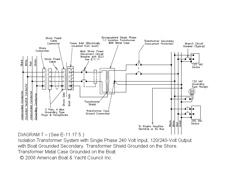
The benefit is that there is no physical connection between the two coils. So the second coil is effectively isolated from the rest of the power grid. This principle can be used to isolate the AC circuits on a boat from the AC circuits ashore.
The green wire on the boat is connected to the white wire on the boat side of the transformer, at the transformer terminal. This is the only exception to the rule about not connecting the green and white wire on the boat! The following diagram from ABYC E-11 illustrates this connection. Click on the image for full size.
References
Wikipedia on Isolation Transformers.
BoatUS on Galvanic Corrosion And Isolation Transformers:
BoatHowTo.com Nigel Calder and Dr. Jan Athenstadt On how to do electrical systems the right way.
Steve D'Antonio on Isolation transformers and Galvanic isolators:
Steve D’Antonio is PassageMaker Magazine's Technical Editor and the VP of operations for Zimmerman Marine, a custom boatbuilder and full-service repair yard in Mathews, Virginia. Published 2006
Some people do not agree that DC Currents are the only cause of Galvanic Corrosion. They believe that stray AC current can also cause significant Galvanic Corrosion. There is an article by Dick Troberg that appeared in the February/March, 2007 Professional Boat Builder, Number 105 called The Other Stray Current. Unfortunately I do not have a link to this article but you should be able to get a reprint from Professional Boat Builder. Tests that he has conducted indicate that AC current can result in galvanic corrosion.
Links to Offsite References:
Wiring Your Boat
Index to all Basic Electricity Pages.
|
|
|
This Web site may contain copyrighted material the use of which has not always been specifically authorized by the copyright owner. I am making such material available in my efforts to advance understanding of educational, economic, and scientific issues, etc. I believe this constitutes a "fair use" of any such copyrighted material as provided for in section 107 of the US Copyright Law. In accordance with Title 17 U.S.C. Section 107, the material on this Web site is distributed without profit to those who have expressed a prior interest in receiving the included information for nonprofit educational purposes. For more information see: www.law.cornell.edu/uscode/17/107.shtml. If you wish to use copyrighted material from this Web site for purposes of your own that go beyond "fair use", you must obtain permission from the copyright owner. |

Ad