
Index to this Page
| Planning | Battery Switches | Bonding | |
| Grounding | References |
Basic Electricity - Page 6 - More Circuits
Basic electricity for boat builders, boat repairers and owners. What you need to know about the electrical systems on your boat. DC Circuits, Planning, Grounding, Bonding, and Battery Switches.
The DC wiring diagram below shows how complex DC circuits can quickly become. So, careful planning and layout is necessary. Before you even begin to wire up your boat you should do all of the following:
Equipment: Determine what equipment you want to have and where it will be mounted.
Power: Determine the power requirements. Make sure you have enough power for everything.
Wire: Make an estimate of how much wire you will need. Don't scrimp on wire.
Plan: Make a diagram of the boat showing where everything will be. Sketch in where you think it will go on the boat. Check it against the boat. You don't want to have wiring going through tanks or appliances, or equipment mounted where you don't have easy access to it. Similar
to this: It does not have to be as complex as this one. It's purpose is to show
where you would like equipment to be. For more information see
14 Steps To Wiring Your Boat, step 8.
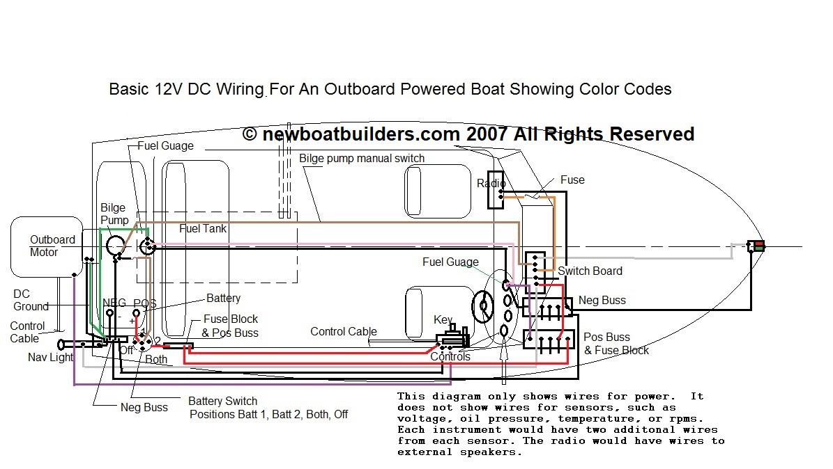
Draw a schematic like the one below, showing wires, over current protection, switches, panel boxes, batteries and everything else in the electrical system. This is a separate diagram showing only the electrical system. It is not the same as the diagram showing where equipment is located on the boat.

See Planning the Electrical System
An excellent article by Owen Youngblood on Wiring Your Boat, from the Metal Boat Quarterly
Calculate wire sizes and fuse or circuit breaker sizes. See Electrical System-Wire Size
DC Grounding Conductor.
When you have a lot of electrical appliances on a boat, to insure proper grounding of the equipment, you can use a DC grounding conductor that runs the length of the boat as shown in the diagram above. On a DC system this third wire is not a necessity, but on an AC system is absolutely essential. This would be a green cable and should be the same size as the cable from the battery to the starter. In some cases a large copper strap is used. In the diagram nothing is connected to the conductor, except the negative ground. But in practice, the metal case of all equipment would be connected to the DC Grounding conductor. This insures a common ground.
Some items that would be connected are; the case of deck windlass, the outside case of a bilge pump, an electric toilet, the case of all electronics. Metal tanks and the tank level sensors are also grounded. But, metal fittings in the hull such as drains, keel bolts, the transducer for the depth sounder and other fittings are not connected to this conductor. See the Paragraph below on Bonding.
Exception: See Fuel Systems paraphrased as follows: Fuel Fill Grounding; A study by IMANNA Laboratories https://www.imanna.com/ has shown that connecting the metallic retaining chain and cap of a plastic body fuel fill assembly to a boats bonding system may result in electrostatic discharge from a land-based fuel pump nozzle to the metallic components of the assembly when the boat is not in the water. This condition does not exist when the boat is in the water due to the equalizations of the ground potentials between the fuel pump nozzle and the boats bonding system. It is recommended by ABYC and the USCG that new and existing installations of this type of fuel fill assembly DO NOT INCLUDE any attachment to the boats bonding system. Existing connections should be removed from the point of connection to the boats bonding system to the fuel fill assembly. Removal of the metallic components of the assembly is not necessary; however, the U.S. Coast Guard and ABYC still require that Metal body fuel fills be bonded.
The DC grounding conductor should not be a return path, that is, the negative side of the dc circuit, back to the battery. The primary purpose of this conductor is to provide an alternative ground path in the case there is a fault inside a piece of electrical equipment. It provides an alternate return path, but only if a short occurs between a positive conductor and a metal case. This should be the only time there is actually current flowing in this conductor. This grounding conductor is not a bonding conductor.
Bonding is a separate system. It provides protection against galvanic corrosion, and if you have a lightning protection system, is connected to a ground plate. See The Connection Between Bonding, Grounding And Lightning
Galvanic Corrosion: As I said at the beginning when describing what a battery is, if you have two fittings on a hull, each of a dissimilar metal, and immerse them in an electrolyte, in this case the water outside the hull, then connect them with a wire, current will flow, and the metal that is the less noble, or lower on the galvanic scale https://en.wikipedia.org/wiki/Galvanic_series, will give up electrons. This is called galvanic corrosion. Soon that metal will be gone. We need a way to prevent this, particularly as outboards and sterndrives are made of aluminum, and many through hull fittings are bronze.
Anodes; Sacrificial anodes are used and bonded to this conductor to prevent galvanic corrosion. In theory, if done right, the anodes give up themselves and everything else is protected. Sacrificial anodes are often generically referred to as zincs, but there are different metals used depending on what you are trying to protect. Some are made of magnesium, others of aluminum alloys. What you use depends on the hull material and what you are trying to protect and whether you are in fresh water or salt water. Consult the manufacturer of your outboard, sterndrive, or engine package.
Bonding is controversial. Some people do not bond the fittings on their boats. They believe it promotes galvanic corrosion. Particularly with metal hulls, the discussion of whether to bond or not is hotly argued. I believe it is a good thing to do, and will provide good protection from galvanic corrosion. See Corrosion On Boats.
I am not going to get deeply into this because it is a very complex subject and not really relevant to basic DC circuits, but you can find out more about this by reading books on electrical systems on boats. It is something you should be aware of. In books on boat maintenance there are often entire chapters devoted to this. This becomes increasingly important if you add AC electrical to your boat.
Battery Switches
In the diagram above are two switches, one next to each battery. These are commonly called battery switches. They are used to switch off all power on the boat. They are not used on all boats. I recommend they be used on any boat with more than a very simple circuitry but mostly they are seen on inboards or on boats with very large outboards.
Federal Regulations do not require a battery switch. However, ABYC requires one for a battery rated at 800 CCA or greater. See ABYC E-11.6.1.2. There are some exceptions such as trolling motor circuits. The switch should be mounted in an easily accessible location but as close to the battery as possible. This is so in the case of an emergency you can easily turn off the DC power and it allows you to easily turn off all power when the boat is not being used.
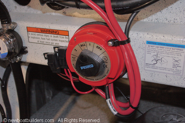
Below are photos of battery switches. They have four positions, OFF, ALL, 1 and 2. When OFF is selected the batteries are disconnected. When number one is selected battery number one is connected. When 2 is selected the other battery, number 2, is connected. This is so you can isolate batteries for use or for charging, or on ALL charge them both.
The ALL position means that if you have two batteries they are both connected in parallel. If your batteries are weak, you can use them both for starting the engine. The switch on the right has a position for paralleling the batteries. This is the same as the ALL position.
Battery Switch Purchasing; Be very careful when selecting battery switches. ABYC 11.1.6.2.3 says "Battery Switch Ratings - The intermittent rating of a battery switch shall not be less than the maximum cranking current of the largest engine cranking motor that it serves. The minimum continuous rating of a battery switch shall be the total of the ampacities of the main overcurrent protection devices connected to the battery switch, or the ampacity of the feeder cable to the switch, whichever is less."
Pick a brand name that is UL Marine Listed. See Blue Seas on UL Marine Listed Battery Switch testing https://www.bluesea.com/resources/119 A few years ago, (the mid to late 90's) the market was flooded with counterfeit battery switches. Many of them simply melted. A few caught fire. Beware and do your research before buying. Don't buy based solely on price. Buy a good quality product.
References
How to Wire A Marine Battery Switch on eHow
 |
 |
Links to Offsite References:
Wiring Your Boat
Index to all Basic Electricity Pages.
|
|
|
This Web site may contain copyrighted material the use of which has not always been specifically authorized by the copyright owner. I am making such material available in my efforts to advance understanding of educational, economic, and scientific issues, etc. I believe this constitutes a "fair use" of any such copyrighted material as provided for in section 107 of the US Copyright Law. In accordance with Title 17 U.S.C. Section 107, the material on this Web site is distributed without profit to those who have expressed a prior interest in receiving the included information for nonprofit educational purposes. For more information see: www.law.cornell.edu/uscode/17/107.shtml. If you wish to use copyrighted material from this Web site for purposes of your own that go beyond "fair use", you must obtain permission from the copyright owner. |

Ad