Index to this Page
| Simple Circuits | Overcurrent Protection | ||
| Circuit Elements | Layout: Neatness | ||
| Types of Circuits |
Basic Electricity - Page 4 - Simple Circuits
Basic electricity for boat builders, boat repairers and owners. What you need to know about the electrical systems on your boat. Basic DC circuits. Power Source, conductors, fuses, switches, grounds.
There are some basic elements to every circuit. There is the source of power, the positive conductor, the negative or return conductor, a switch, overcurrent protection, and the load. See https://eschooltoday.com/learn/electrical-circuit/
Source of Power:
Generally the source of power is a battery or a battery bank. If the engine is running, the source may be the alternator. For larger boats with many electrical devices the source may be a converter, or an inverter, or from shore power. Some boats also have an onboard auxiliary generator. A buss bar or fuse block can also be considered the source of power for a specific circuit.
Conductors are generally wire or cable, but there are other conductors such as circuit boards, distribution boards or buss bars. The simplest circuit has a positive wire going to the load, and a negative wire coming back. However, this would hardly be practical because the power would always be on. So there are generally two other devices in a circuit.
Overcurrent Protection (Fuses or Circuit Breakers)
The first is a fuse or circuit breaker. See Marine Fuses and Circuit breakers. https://www.bluesea.com/resources/95 The fuse should be as close to the power source as possible because its job is to protect the wire to the load. On recreational boats with permanently installed gasoline engines, this is required by regulation in 33 CFR Subpart I: Sec. 183.455, Electrical Systems. This is the ABYC standard for all boats in ABYC E-11, AC and DC Electrical Systems on Boats.
Switches:
Then there is a switch to turn the device on or off. Here is a diagram of a simple circuit.
 |
All DC circuits are based on this simple model.
Here is another simple circuit diagram that is slightly more detailed.
 |
Ground:
As you can see the negative wire from the battery is connected to the outboard engine. It would be connected to the block if this were an inboard engine. This establishes the ground.
Series Circuits: Remember those Christmas tree lights that when one light failed, they all went out? Then you had to check every light on the string until you found and replaced the bad one? That's a series circuit. If it had been a parallel circuit the good lights would have still been lit. Generally on boats there will be only one electrical item on a series circuit such as, a bilge pump, a cranking motor, or a blower. If you have two or more, the voltage reduces at each item and you may not have a high enough voltage to run the equipment that is at the end. Also, if there is a break in the circuit, or one item goes bad, they all stop working.
Parallel Circuits: In a parallel circuit there may be many devices on the circuit. As in the circuit diagram above, the navigation lights are in parallel. On larger boats you may have several electronic items or instruments on a parallel circuit. The voltage stays the same in both legs of the circuit. Resistance is reduced. Plus if one item fails the others keep on working.
Series and Parallel Circuits:
|
|

Batteries are not the only electrical component that can be wired in series or parallel. Electrical devices on a circuit can be wired in series or parallel as well. Parallel circuits are very common on boats, especially with lighting. It decreases resistance on the circuit and decreases voltage drop; In the diagram above the navigation lights are in a Parallel Circuit. Most of the other items are in a series circuit. Below is a typical Parallel Lighting Circuit and a Series Lighting Circuit. Each has advantages and disadvantages.
Overcurrent Protection:
In the circuit diagrams above there is a fuse or circuit breaker near the battery. ABYC standards, Federal Regulations, and ISO say it has to be within seven inches (17.8 cm)of the source of power. This protects the wire between the battery and the positive distribution buss.
 |
 |
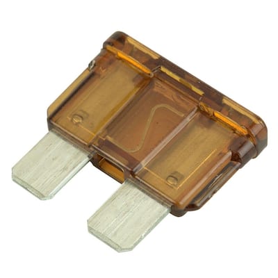
This is an important point that is often misunderstood and needs to be repeated. Fuses and circuit breakers protect the wires, not the equipment. The danger is that the wire will get too hot, melt the insulation, and start a fire. The image to the right shows Typical fuses:
If you look at the positive distribution buss, you will see that there is also overcurrent protection immediately after the buss. That is because the buss is considered the source of power for the connected equipment. It too must be within seven inches (17.8 cm) of the buss bar. There are exceptions. See Over Current Protection on Electrical Systems Page 1
After that there is a switch to turn the equipment on or off. An exception is the bilge pump. Bilge pumps are usually wired directly. Most have a built in float switch, that turns the pump on when the water gets to a certain level and a bypass switch to turn it on manually. Bilge pumps may have a small in-line fuse that protects the pump from burning out if something clogs the pick up and water stops flowing.
Buss Bar; Below is a typical distribution buss bar. This one is in the negative or ground side of the circuit. The large wire connected to the bolt on the left end is the wire from the negative post on the battery. All the other wires are negative wires to various pieces of equipment.
Neatness:
By the way, notice how neat and tidy and organized this is. Wiring should always be organized and neat. The only thing that would make this better is a tag or label for each wire naming what equipment it connects to. Making your wiring neat and tidy accomplishes several things. It keeps wires from swinging and swaying and protects them from abrasion. It also makes it far easier to trace out a circuit and find and correct problems.
|

Index to all Basic Electricity Pages.
|
|
|
This Web site may contain copyrighted material the use of which has not always been specifically authorized by the copyright owner. I am making such material available in my efforts to advance understanding of educational, economic, and scientific issues, etc. I believe this constitutes a "fair use" of any such copyrighted material as provided for in section 107 of the US Copyright Law. In accordance with Title 17 U.S.C. Section 107, the material on this Web site is distributed without profit to those who have expressed a prior interest in receiving the included information for nonprofit educational purposes. For more information see: www.law.cornell.edu/uscode/17/107.shtml. If you wish to use copyrighted material from this Web site for purposes of your own that go beyond "fair use", you must obtain permission from the copyright owner. |

Ad