
Index to this Page
| Definitions | Connections | Wire Sizing |
| Ignition Wire | Overcurrent Protection | Wiring Diagrams |
| Protecting Conductors | Special Applications | References |
Electrical Systems: Page 2
Page 1, Amperage Table on Page 3 >>
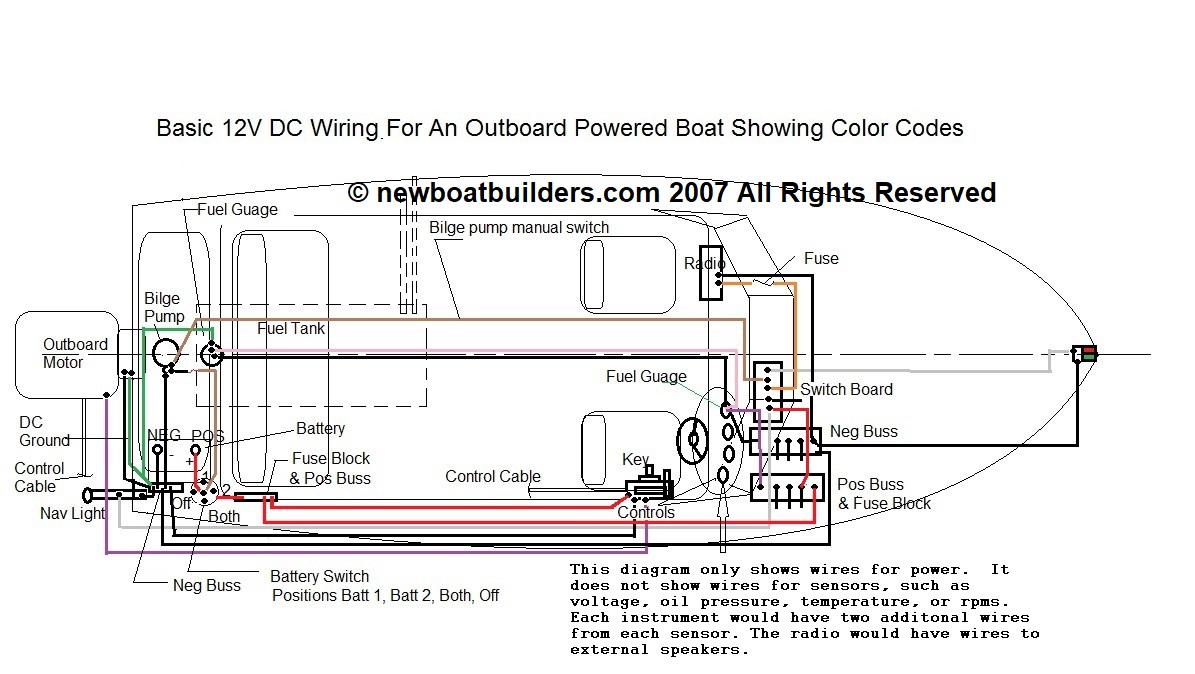
Electrical regulations and standards that apply to boat builders and recreational boats. Ignition wire, conductors, over current protection, wire sizes, fuse sizes. Definition - Regulations: When referring to laws, that is, Federal Regulations or Statutes, I will use the word Regulation and/or use a citation such as CFR 183.501, Code of Federal Regulations section 183.501 or USC 4301 (United States Code Subchapter 4301). Definition - Standard: Industry standards will be referred to by the name of the standard organization such as ABYC, SAE, UL or NFPA. In most cases these standards are voluntary and not law. However, beware! Almost all of them are the accepted practice by the industry and used by builders, marine surveyors, marine investigators, and attorneys as the de facto standard. If you choose not to follow the standards you should be prepared to defend why your practice is as good or better. See my page on ABYC See Also Standards Societies. Ignition Wire:. See US Coast Guard Regulations 33 CFR Subpart I: Electrical Systems Sec. 183.440 Secondary circuits of ignition systems. (a) Each conductor in a secondary circuit of an ignition system must meet SAE Standard J557. Since this regulation was published the standard has changed but the Coast Guard has not updated the Federal Regulation to match the SAE standard. SAE standard J557 no longer exists. The current SAE standard for marine ignition wiring is SAE J2031, which also covers road vehicle ignition wiring. (b) The connection of each ignition conductor to a spark plug, coil, or distributor must have a tight fitting cap, boots, or nipple. ABYC standard P-4 Marine Engines and Transmissions Says. 4.6.14.4 High tension ignition cable assemblies shall conform to SAE J1191, High Tension Ignition Cable Assembly. 4.6.14.5 Ignition distributors shall conform to SAE J1294,Ignition Distributors or UL 1120, Marine Engine Ignition Systems and Components. So all ignition wiring, wiring assemblies, distributors and the boots, caps, and nipples should be made for marine use. If you purchase engine packages from one of the marine engine suppliers then the engine wiring will be pre-installed and meet all of these standards. You are responsible for making sure wiring leading to the engine complies with the regulations. However, if you do your own marinizing or engine rebuilding then you must make sure the wiring on the engine is up to the standard. Protecting Conductors: 33 CFR 183.455 Wires need to be protected from shock, vibration, abrasion, and flexing. In addition, they should be laid out so they do not make sharp corners. They should be laid out neatly so there is easy access, and easy replacement, and do not make contact with hot parts such as exhaust manifolds, or hang in the bilges. (a) Each conductor or group of conductors that passes through a bulkhead, structural member, junction box, or other rigid surface must be protected from abrasion. Wires should be supported using clips or straps, at least every 18 inches (45.5 cm), throughout their length. Where they pass through bulkheads or other structure they must be protected from abrasion by grommets or some other non-abrasive material. (b) Each ungrounded terminal or stud that is continuously energized must meet CFR Sec. 183.455 or must have a boot, nipple, cap, cover, or shield that prevents accidental short-circuiting at the terminals or studs. Positive terminals, such as the positive terminals on the starter, solenoid, alternator and other electrical equipment must be covered with a rubber boot, cap or nipple so that metal tools won’t accidentally come in contact with them. Battery terminals were already discussed, but just as a reminder they need to be covered as well. The amount of energy released when a wrench or screwdriver accidentally comes in contact with one of these terminals can be truly frightening, and start a fire or cause an explosion if fumes are present. Connections:. ABYC Standard E-11: Solder must not be the sole means of connection between two or more conductors or between a conductor and a connector. What? I can't use solder? Yes you can, BUT, it must not be the only connection. You must also have some sort of mechanical connector, such as crimp type connectors, that hold the two wires together. When you solder the wire it becomes essentially a solid single conductor wire. It forms a hard spot in the wire that concentrates the stress at that point and becomes prone to breaking. So use a connector as well as soldering. Some marine wiring experts even advocate not using solder at all. But this is a matter of opinion. Some think the acids in the solder cause corrosion, others disagree. So if you do solder, use an acid free solder and make sure it is good solid solder not a "cold solder" The same applies to connectors inside of junction boxes and electrical panels. DO NOT USE WIRE NUTS! They do not supply a good mechanical connection and they are prone to vibrating off. They also allow moisture to collect inside the wire nut, causing accelerated corrosion of the wire. The corrosion raises the resistance of the wire creating heat, and causing a large voltage drop at this point, which means you will not be getting full voltage down stream, at the appliance. Low voltage at the motor, light, or other appliance you are running causes the item to overheat and burn out. This is another item that was in the Federal Regulations, but was taken out in the deregulation process. However, it is still good practice not to use wire nuts. There are some manufacturers of wire nuts who claim their product can be used on boats. Don't do it. They have the same problems as regular wire nuts. ABYC Standard 11.16.3.6. is very specific: Twist on connectors, i.e., wire nuts, shall not be used. Exception. Sometimes wire nuts are used inside of appliances such as refrigerators and washers and dryers. These do not have to be removed. OVER CURRENT PROTECTION:. 33 CFR 183. 455 Each ungrounded current carrying conductor must be protected by a fuse or by a manually reset trip-free circuit breaker. This means that the hot wire, that is the positive wire in DC systems, must be protected. The negative wire does not have to be protected. There is often confusion here. The circuit breaker or fuse is not there to protect the motor or appliance. CIRCUIT PROTECTION IS THERE TO PROTECT THE WIRE. Too much current in the wiring causes it to get hot, melt the insulation and start a fire. If there are still any positive ground systems out there in the world, everything is then reversed from what I am saying here. Manually reset trip-free circuit breaker: What in the world is a manually reset, trip-free circuit breaker? Obviously it is a circuit breaker, but what does the rest mean. Well, it means it can't automatically reset itself. You have to manually reset it. Trip free means you can't hold it in the on position while there is still a fault. If the circuit is going to trip the breaker, it must trip whether you are holding it place or not. Look for the UL MARINE listing on the package. DO NOT USE circuit breakers intended for house wiring! They are not designed for marine use and are not ignition protected. DO protect all circuits. The only exception is the starter motor circuit. However, since I wrote this 20 years ago, there are now available on the market, circuit breakers that are designed specifically for starter motor circuits. These may be used, but are not required. Location of Overcurrent Protection 33 CFR 183.455 The fuse or circuit breaker must be within seven inches (17.8 cm) of the source of power. Exceptions: Exception 1. If it is physically impractical to put the fuse or circuit breaker within seven inches of the source of the power it can be up to 40 inches (101.6 cm) away, if the wire is contained for it's entire length between the source of power and the circuit breaker, in a sheath or an enclosure. This has been interpreted many ways. The obvious is a conduit. But who uses conduit on a boat? Conduit might be used on really big boats. Putting a sheath such as wire loom or heat shrink wire covering over the wire works. Some even say that wrapping it in electrical tape is ok. I think that this is really a shoddy way to do it and not very professional. There are many different wire sheaths available, some that are fire resistant. Also if the wire is in an enclosure such as a panel box or electrical box then it is ok. The whole idea here is to protect the wire in such a way that if it overheats it doesn't set the boat on fire. Here are some links so you can see what I'm talking about. The following links are not an endorsement of these products. The are just presented as examples of products available. Exception 2. Each ungrounded output conductor from a storage battery must have a manually reset, trip free circuit breaker or fuse, unless the conductor is in the main power feed from the battery to the cranking motor. The fuse or circuit breaker must be within 72 inches (182.9 cm) of the battery, unless it has a battery disconnect switch. The above distances are measured along the wire. In other words we are talking about wire length, not the straight line distance from the power source to the fuse or circuit breaker. Also note, this is only in the output conductor (wire) from the battery to the cranking motor (starter). The obvious solution here is to install a battery switch as close to the battery as possible and that is what most boats have. Just make sure you use a good quality UL listed switch. There are a lot of cheap, poor quality fakes on the market. Buy a good brand name. Why? Because a lot of current flows through this switch, and when the switch is thrown sometimes arcing occurs. You want a switch that can stand up to this. I have seen cheap ones that melted or caught fire. Sizing Circuit Breakers or Fuses: 33 CFR 183.455 Circuits of less than 50 volts: (DC Circuits) A circuit breaker or fuse should not be rated for more than 150% of the amperage that the circuit is rated for. Suppose you have a 30 amp circuit. Then the circuit breaker or fuse should be no more than 45 amp. This is so it will blow, but not blow for the occasional spike in current that occurs when you first turn on a piece of equipment. You don't want it rated higher than this because then the wire may burn before the breaker trips. Circuit breakers in low voltage DC circuits should break only the positive wire. If you break both wires you break your connection to ground. Circuits of 50 volts or more: (AC circuits or high DC voltage circuits) The circuit breaker or fuse should be sized at the same amperage as the circuit. If you have a 30 amp circuit then the breaker or fuse should be 30 amps. If you can't get the exact size then it should not exceed 150%. But it is best to rate it at the amperage rating for the circuit. Circuit Breakers in AC circuits should be double pole, that is, break both the black and white conductors at the same time. In AC this important because if you do not break both the hot and neutral you may still have a hot circuit. This is dangerous to a person working on the system. For all circuits the voltage rating of the fuse should be the same as the circuit voltage. It the circuit is 12 volts then the breaker or fuse should be 12 volts. If it's 110 volts then it should be rated for 110 volts. Do not mix breakers. Yes, you can use a 110 volt breaker on a 12 v circuit, but definitely don't use a 12 volt breaker on a 110 volt circuit. But you should use a breaker or fuse sized for the correct voltage. Special Applications: There are some special circumstances that permit a variance from the above. If it is the power feed from the battery to the starter it does not have to be fused. However, make sure the wire is sized correctly because this circuit carries a lot of current when you try to start the engine. Also try to locate the battery so that this wire is as short as possible. Don't get fanatic about it, but the shorter it is then the less resistance the wire has and the more power you get to the starter. If the alternator or generator is not self-limiting then there must be a fuse or circuit breaker on the output. The breaker or fuse cannot be rated for more than 120% of the maximum current output at 60 degrees C. Today most engines have alternators (AC) rather than generators (DC) and most alternators have a built in regulator that makes them self-limiting, but there are still some around that aren't. This is generally not something the boatbuilder or owner has to worry about because most buy an engine package from one of the engine manufacturers and all this is done by them. But you should be aware of it. If the alternator or generator is self-limiting then this requirement doesn't apply. Ask the people you buy the package from if the alternator is self-limiting, that is, does it have a built in regulator. WIRE SIZES: 33 CFR 183.425 For wire sizes see the table listed below. Table of Allowable Amperage of Conductors What do we mean by wire size? It means the actual physical size of the wire in mils, usually stated as wire gauge. Simply, how thick or thin is the wire? The concern here is resistance and voltage drop. Resistance and voltage drop are caused by two things, the size of the wire and the length of the wire. The thinner the wire the more resistance it has and the longer the wire the more resistance it has. So, there is not much you can do about the length of the wire except move things closer but that is often not an option. So then you have to size the wire so that it has the least resistance and least voltage drop. Here is link to Wikipedia that explains American Wire Gauge. Why? All electrical and electronic equipment is designed to work at a specified voltage. If the voltage is too high it can burn out the equipment. If the voltage is too low it can also burn out the equipment. We are concerned with too low. If a wire has too much resistance the voltage will drop from the high of say 12 volts to maybe 11 or 10 volts at the other end. For example, starters require a constant voltage and high current. If the voltage drops, they slow down, and get really hot. So we need to make the wire the right size to give the starter the right voltage. This also causes the wire to heat up and if it gets too hot, melt the insulation and set things on fire. Wire comes in various sizes from really big at 000 gauge (ga) (sometimes shown as 3/0) to really small at 22 gauge and even smaller sizes. The smaller the size the bigger the number of the gauge. On a boat, the smallest you can use is 16 gauge. Except, you may use 18 gauge in sheathed wire bundles. This would make you think, the bigger the better. That's not the case. The best way is to determine the wire size you need and then go one size bigger (smaller gauge). For example battery cables are typically 4 gauge but can be as large as 0 gauge. It depends on the battery capacity. 22 Guage is allowed on circuits on engines, that control the engine such as ECUs (Electronic Control Units: e.g., computers) Basic Wiring Diagram
Planning your DC Electrical System: See sample US Coast Guard Wiring diagrams: Basically that's it. These are the requirements. But remember that this is the minimum you must do. If you really want to do electrical systems right it is best to follow: Also on Ike's List of Electrical Links you will find references to electrical sites on the internet, and references for books on electrical systems for boats. References: Some excellent web sites for boat electrical questions:
Marine Electrical Checklist (PDF format) from Port Credit Marine Surveys 33 CFR Subpart I: Electrical Systems TP 1332: CONSTRUCTION STANDARDS FOR SMALL VESSELS Section 8 Electrical Systems Canada Standards for small craft. ISO Standard 10133: Small craft — Electrical systems — Extra-low-voltage d.c. installations International Standard For small craft ISO Standard 13297: Small craft — Electrical systems — Alternating current installations International Standard For small craft 46 CFR Subchapter T Part 183 Electrical Installations: Passenger Vessels under 100 Gross Tons. Page 1, 2, Amperage Table on Page 3 >> Index to all Electrical Regulations Pages and Basic Electricity Pages. |
|
|
|
|
|
This Web site may contain copyrighted material the use of which has not always been specifically authorized by the copyright owner. I am making such material available in my efforts to advance understanding of educational, economic, and scientific issues, etc. I believe this constitutes a "fair use" of any such copyrighted material as provided for in section 107 of the US Copyright Law. In accordance with Title 17 U.S.C. Section 107, the material on this Web site is distributed without profit to those who have expressed a prior interest in receiving the included information for nonprofit educational purposes. For more information see: www.law.cornell.edu/uscode/17/107.shtml. If you wish to use copyrighted material from this Web site for purposes of your own that go beyond "fair use", you must obtain permission from the copyright owner. |

Ad