
Rebirth of a 1972 18' Sea Ray 190 I/O Pg 4
Spring 2013: More Engine, exhaust and Cooling System Work.
When I last ran the boat in November, the engine compartment ventilation blower failed to work. The problem turned out to be the blower switch, but since the blower was forty years old I decided to replace it and the switch.
Ventilation:
Fix collector box: When I examined the bottom of the collector box, the wood piece had come loose, so I had to reattach it first before I could install the blower. I used 3M 5200 to glue the bottom piece (wood) to the collector bottom (metal) and then clamped it and added four screws, two on each end. I then installed the new blower. The new blower was similar to the old one, but slightly larger and had a different pattern for the screws that hold it in place. Once it was in place, I attached the wiring to the pigtails coming out of the blower.
New Blower Switch: At the dash I installed a new blower switch. After hooking everything up, I tested it and the blower worked perfectly, and is very quiet.
Fuel problems: I put the boat in the water, and it fired up on the first crank, but after running for a few minutes (maybe five minutes) it died and would not restart. After checking all the usual stuff (electrical, fuel, air) I determined it was water in the gas. Over the winter it sat collecting moisture in the tank. So how do you get it out? I bought a small hand pump for pumping gas at an auto parts store.
DO NOT USE AN ELECTRIC PUMP FOR THIS. It could cause a spark which would ignite the fuel vapors and cause an explosion.
I pumped about a gallon from the bottom of the tank. It has to come from the bottom because that is where the water is. I inserted the suction hose into a copper tube so it would go straight to the bottom without bending. I put the suction hose down the fuel fill all the way to the bottom of the tank. I pumped the fuel into a small gas can. I also drained the fuel that was in the fuel hose, from the tank to the fuel pump, into the gas can. Why do you need to do this? Because there is still bad gas in the fuel line, and it would take several minutes of cranking to get it out. But, be careful when doing this. Use a small plastic bottle or container under the fuel pump to catch the fuel and any drips. Try not to spill any gas into the bilge. If you do, clean it up rght away and properly dispose of the cloth you use to clean it up. Leave the engine compartment open for the day to ventilate any vapors.
DO NOT USE A VACUUM CLEANER TO CLEAN UP FUEL FROM THE BILGE. It will cause a spark and an explosion. If you spill a lot of gas, more than a few cups, call the fire department.
Re-attach the fuel hose. Make sure it is securely attached so there will not be any leaks. The first time you start the engine check the fuel connection at the fuel pump for leaks.
So what do you do with the bad gas?. Do not dump it out or dump it down a drain. You need to find a hazardous materials site that will take it off your hands. You may have to pay for this, but most states, cities, or counties have these services.
Afterwards, the engine started on the second or third crank and ran fine with no leaks.
Testing; I ran the boat for about ten minutes but it was still overheating.
More Engine Cooling and Exhaust Work:
I still needed to put in a new riser, and I had installed an auto part circulating pump. I decided to change this out for a marine pump. I also decided to pull the thermostat out and test it.
New Circulating Pump:
Difference between Marine and Auto Parts: Circulating Pump. Much has been said about the use of marine parts versus auto parts on on-line forums and web sites. It is obvious to most people why electrical parts need to be marine. The parts, such as starter, alternator, blower motors, all need to be ignition protected, that is; not capable of sparking and causing an explosion when gas fumes are present. But what about a strictly mechanical part like a water pump?
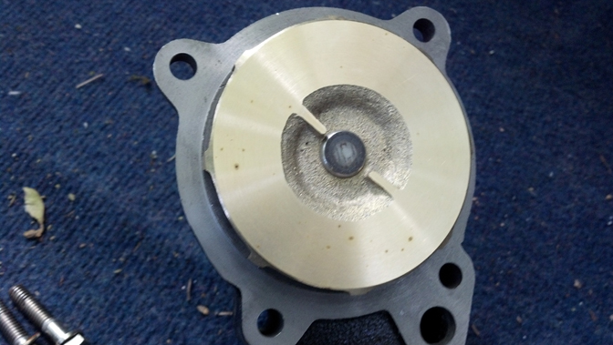
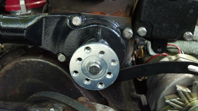
The two pumps outwardly look the same but they are different. The interior parts (the parts exposed to coolant) on the auto part, are not rust resistant. Auto circulating pumps also have a lower flow capacity than marine. Marine pumps have bronze pump impeller and stainless steel parts on the inside. Also, marine parts tend to be heavier construction because of the continuous loads on marine engines. The following photos show the construction differences. The first two photos show the bronze pump impeller and the stainless steel flange that the pulley attaches to. The auto pump in the third photo began to have serious rust after six months.
 |
 |
 |
Checking Thermostat:
I disassembled the thermostat housing and took out the thermostat so I could test it. The test is simple. Put it in a pot of water and heat up the water. The thermostat should open at the temperature marked on it, in this case 140 degrees F. You need a cooking thermometer you can insert into the water to measure the temperature. This one opened at exactly 140 degrees, so it is operating properly. I reinstalled the thermostat using a new gasket.
Installing Riser: Installing the Riser is straight forward. I found that it was easier to attach the flexible exhaust tube to the riser first. Then put the riser on the top of the manifold and insert the flexible exhaust tube on to the exhaust tube. Tighten the clamp bands on the flexible tube. Use only 360 stainless steel bands. It sounds a lot easier than it is. Getting the flexible hose onto the exhaust tube is difficult because the exhaust tube is oval. Then insert the bolts into the riser and position the riser over the bolt holes and tighten the bolts. On another boat it may be easier. On this boat there is not a lot of room to work in and you have to do it lying down with your head under the rear deck.
|
|

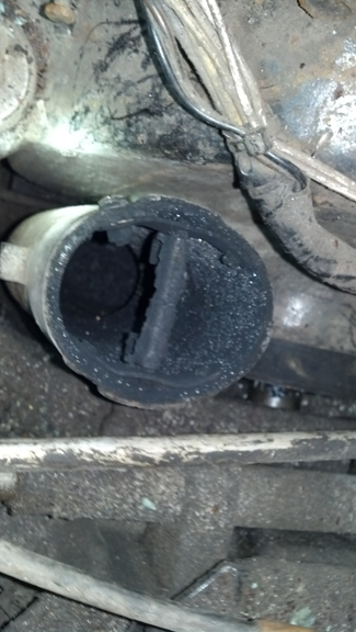
No water Shutter: When I had removed the old riser I had discovered that the exhaust water shutter was missing. I checked as much of the exhaust as I could for pieces. I used a vacuum to clean pieces and debris out of the exhaust. I also removed the prop, and inside the exhaust behind the prop I found a large part of the water shutter. The remains of the exhaust shutter are in the first photo. The second photo is the piece I found behind the propeller.
 |
 |
Testing on Earmuffs: I retested the engine by running it with the earmuffs on the stern drive and a hose attached. There is still a very reduced flow of water, so the restriction has to be in the stern drive. Either the impeller is no good or the water passages are blocked. I am taking it to Commencement Bay Marine to check out the stern drive.
Content Continues After Ad
Two weeks later: Boat is back after repair. They took off the stern drive. Cleaned out all water passages. Replaced impeller. Replaced a seal, Adjusted shift. They ran it for about 20 minutes and it ran cool. I took it out for a test . Engine runs cool. We were out for about one hour. Did not run it over 1500 rpm though. Engine runs a little rough. It started right away when cold, but it was hard to start when hot. The boat takes on water at about one gallon per hour. It is easily handled by the bilge pump.
Ignition System: I installed a new coil and ballast resister, and new spark plugs and spark plug wires. This helped steady the rpms considerably.
Alternator: The alternator was not charging. The new alternator was a three wire alternator rather than a one wire. The difference is thus. An alternator needs a small amount of current to start generating large amounts of current in it's windings. On some alternators this comes from permanent magnets, "exciting" a current in the windings as they turn through the magnetic field. They are called self exciting, and the current is called excitation current. These need only a single wire coming off the back of the alternator to deliver current to the battery. The point where this wire connects to the back of the alternator is labeled on the alternator as B+. So they are called one wire alternators. This is really a misnomer because there is also a ground wire which is attached to the case of the alternator called B-.
Other alternators use electromagnets for excitation current. That is, the magnetism is created by a small amount of current in a coil wrapped around a metal core. The current comes from the battery so there are two more wires attached to the back, thus a three wire alternator. This current has to be limited and "on" only when the ignition is on, so I needed to know where to connect the excitation wires into the boat's ignition system.
The connections can be different for different alternators but generally there is a red wire which is the positive connection and a purple wire that goes to the negative side of the ignition circuit. Since the output wire for the alternator goes directly to the positive pole of the battery (a red wire with a white stripe), the red excitation wire (no white stripe) can also be connected to B+. However, where to attach the purple negative wire depends on how your boat is wired. It needs to be connected at a point where there is no current in the negative when the ignition switch is off, and on when the switch is on. The obvious place to connect the purple negative wire is to the negative connection on the ignition switch. But that may be many feet away and might require a very long wire run. On my boat the closest place is on the engine, on the negative side of the ignition coil, but before the ballast resister. This means it takes only about 3 feet of wire and it is easy to get to and connect.
I needed to find a diagram to confirm my analysis of how to wire the circuit. The Mercruiser owners manual does not have a diagram of how the alternator is wired and none was provided by Mallory when I bought the alternator. E-mails to Mallory's tech support yielded nothing. Obviously I was on my own. But eventually I found a diagram for a Delco style alternator (which is what I had) that seemed to be correct, so I hooked it up and it worked. It was a Eureka! moment.
Of course the true test is starting the engine and seeing if the alternator is putting out and nothing smokes.
Some helpful links:
Wiring a GM 3 wire alternator:
Also, there is an excellent section on testing alternators in Ed Sherman's Book Powerboater's Guide To Electrical Systems which you can buy through Amazon, or download as an e-book. I bought the Kindle version and have it installed on my Android phone, so it is now always available as a reference.
|
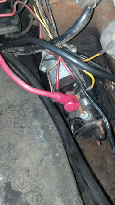
Other Electrical: I added a protective boot over the positive lead on the starter solenoid. This is required by law and prevents any inadvertent contact with metal tools.
Future Electrical: Replace all wiring. Install fuses and re-directing wiring through the fuse block. Replace more switches on the dash.
Other upgrades: The Carburetor was completely rebuilt. The carb is a Rochester 2GC, 300 CFM. These were very common in the 70's but are not so common anymore. However, because they are still in wide use, parts and information on them is widely available. The manual is available on line for free However, this manual is for the automotive version and there are differences in the marine version. But, many parts sellers carry the marine versions of this carburetor. See also the Carburetor Doctor
There was water leaking into the engine (and into the oil) through the gasket between the manifold and the riser. The gasket was replaced. Replaced 12V socket on instrument panel. Replaced outboard motor mount with one that can be raised and lowered, and replaced outboard with a 4 HP Mercury (under the skin it's a Tohatsu). Plugged all the old holes in the transom. There were holes for at least two different motor mounts. Repaired the speedometer so it now works. I continue to fix or replace anything that doesn't work.
August 2014: What she looks like now.
|
|


|
|
|
This Web site may contain copyrighted material the use of which has not always been specifically authorized by the copyright owner. I am making such material available in my efforts to advance understanding of educational, economic, and scientific issues, etc. I believe this constitutes a "fair use" of any such copyrighted material as provided for in section 107 of the US Copyright Law. In accordance with Title 17 U.S.C. Section 107, the material on this Web site is distributed without profit to those who have expressed a prior interest in receiving the included information for nonprofit educational purposes. For more information see: www.law.cornell.edu/uscode/17/107.shtml. If you wish to use copyrighted material from this Web site for purposes of your own that go beyond "fair use", you must obtain permission from the copyright owner. |